Single Digit VFD Clock
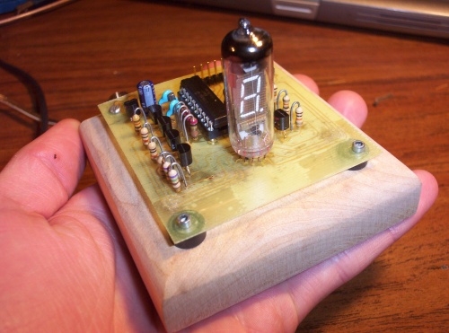
I built this single digit vacuum florescent display (VFD) clock out of some tubes I got off eBay. I got the inspiration from Jon's page here.
I got 10 of these tubes off of ebay for pretty cheap. The goal was to make a nice looking clock with all electronics visible. The circuit it self is quite simple - to get decent brightness out of these particular tubes each segment has to be driven with 12v. Actually it's a little closer to 15v with the wallwart I'm using. Since the PIC can only supply 5v, PNP transistors are used to drive each segment and are biased such that the 5v from the PIC is enough to turn them off but 0v is enough to put them in saturation.
I draw the circuit out in Eagle, route the board, and then print it on magazine paper with a laser printer. I've found the IEEE spectrum magazine to be perfect - use the ads of course, not the articles :-) Turn up the contrast on the printer and remove any 'economy' settings - you want as much toner on there as possible. Then prep the coperclad board. I rough it up a bit with a scotchbrite pad and then clean it very thoroughly with acetone. Now lay the printout on top of the board and warm up the iron. I use a clothes iron set to max temperature. The idea here is to press down firmly, evenly distributing the pressure. I find a kleenex inbetween the iron and the paper helps with this. After a couple minutes of ironing, I throw the whole thing into the water and let the paper get nice and soft.
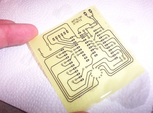
Once the paper is good and soggy, gently pull it off and the toner should be left behind, stuck to the copper. The toner resists the etchant protecting the copper underneath and ultimately forming the traces. This one is almost perfect except the few broken traces. I've rarely had them turn out completely perfect, but minor issues like this can easily be fixed with a sharpie - it resists the etchant surprisingly well.
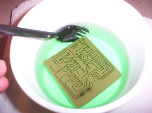
Next up is to put the whole thing in an etchant solution. I use a 2:1 mixture of hydrogen peroxide and muriatic (HCl) acid, respectively. This stuff is pretty powerful and will etch the board in a few minutes especially if it's slightly warm. The plastic spoon is for agitating the board around a little. You definitely don't want to use a metal one! Also have a little bit of ventilation around as it produces a little bit of chlorine gas. A nice explanation to how this works is here. I particularly like it since it's extremely cheap and readily available.
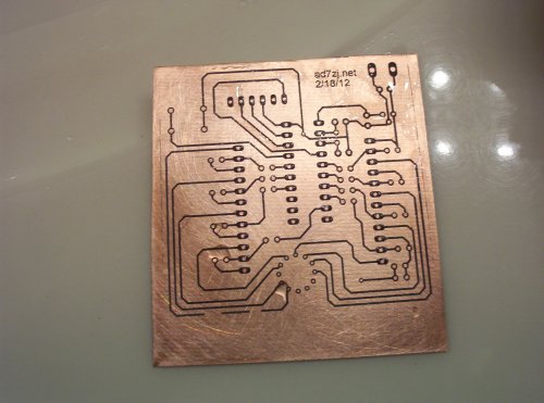
Here's a shot of how it looks after etching with the toner still on. At this point I use acetone to remove the toner. Since these are all through hole components, there's lots of drilling to be done! I bought a bunch of resharpened PCB drills off ebay for a few dollars and stick them in a drill press. The higher RPM the better... I think my drill press tops out around 4000 rpm and that seems to work fine. I haven't broken any yet, anyways :-)
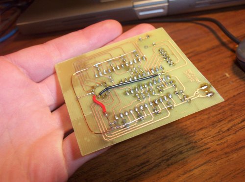
Since this was going to be etched by hand, I was trying to get as much as possible on a single layer. That accounts for some of the sloppiness in the schematic, as it is wired up so as to avoid wires needing to cross over each other. As it worked out, I was able to route it entirely on a single layer, save some of the power connections. Those are the additional wires soldered onto the bottom of the board.
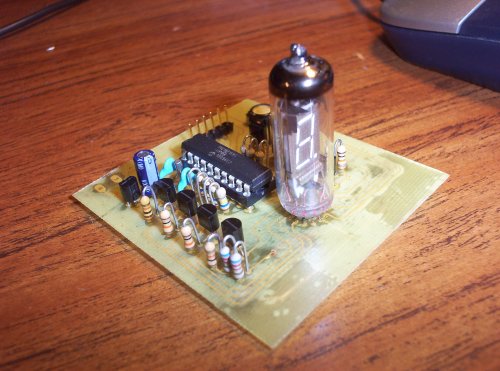
And there it is, all finished :-) I'm powering it with a 12v wallwart, which has worked pretty well. The software is written in C and built using the Hi-tech compiler for the 10/12/16 PICs. It's not the most beautiful in the world, but I was in a hurry to get it working :-) It's really very simple though, how complex can a clock possibly be? The schematics and board layout are done using Eagle. All of this is in a git repository linked below.
