Grimes Strobe Repair
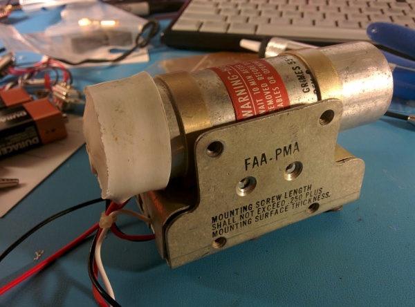
Fixing a Grimes 60-2250-1 wingtip mounted strobe power supply. A little research didn't turn up anyone still servicing these or selling them so I decided to have a go at it myself with good results.
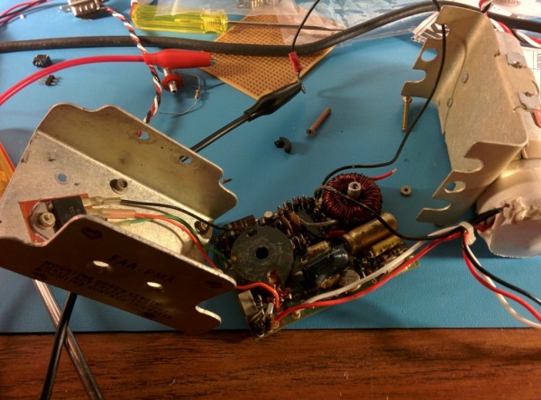
Pop the case open, here's what it looks like.
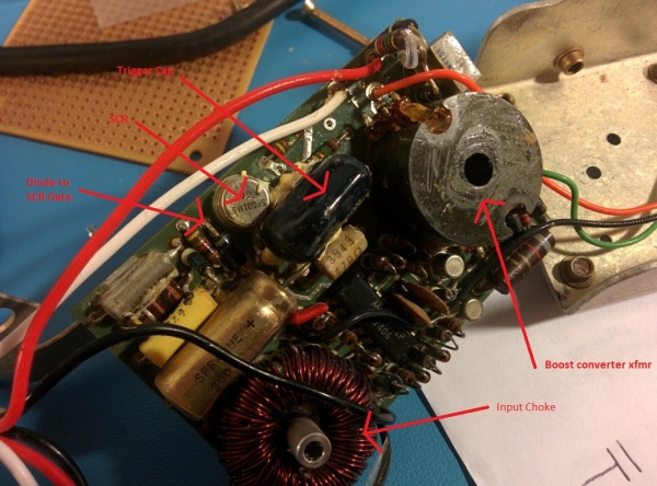
Obviously be careful poking around in there with it powered up, as most of you probably know that big capacitor gets charged to a high voltage (about 480v in this case). While it might not kill you, it certainly has the potential to do some damage so treat it with respect :-). Only use one hand while probing stuff. The board is doing two major functions: 1) taking the 12v input and charging the big capacitor up to 480v and 2) generating a trigger pulse to start the Xeon flashtube. The flashtube ends are connected directly to the large capacitor and once the arc is started, it goes until the capacitor voltage drops to where it'll no longer sustain (80v or so I saw). There is a tiny transformer in the base of the flashtube that multiplies the 250v trigger pulse pulse up to several thousand volts which is applied to that that thin wire wrapped around the tube. That high voltage pulse starts the arc. I labeled the major parts... (click to enlarge)
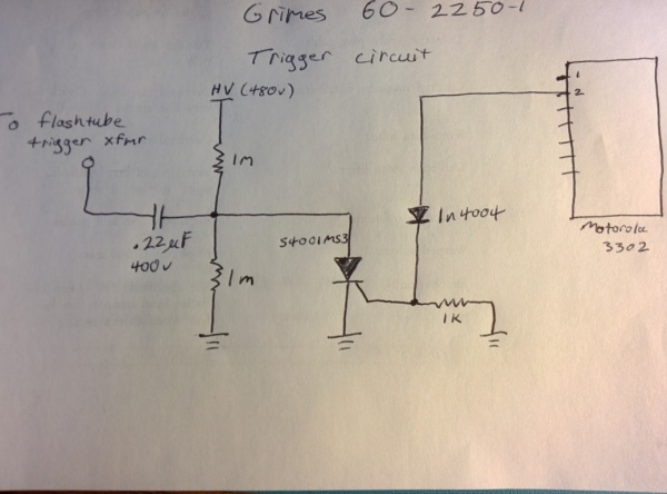
I traced the trigger circuit to see how it works... The only IC on the board is a Motorola quad comparator. Among other things it generates a trigger pulse approximately every second to flash the bulb. I believe at least one other comparator is used in the boost converter. The capacitor was charging properly for mine though so I didn't bother to trace that part :-)
Anyway, pin 2 of the comparator IC drives the gate of an SCR through a 1n4004 diode. The .22uF cap is what generates the trigger pulse. The two 1meg resistors divide the high voltage supply in half and charge the trigger cap, one side of which is connected to the trigger xfmr in the base of the flash bulb. When the SCR fires pulling its side of the cap to ground, the sudden voltage change excites the transformer and that gets the whole thing going. SCRs have an 'avalanche' effect in that once you turn it on, it turns on hard and stays on until the forward current dies away. This hard turn on is perfect to generate a very fast pulse on the order of a few uS.
In my case the diode the comparator drives the SCR through was apparently damaged as there was hardly any trigger pulse on the SCR gate - not enough to fire it. I replaced the diode and viola, it works again! I went ahead and replaced the SCR and trigger capacitor while I had it pulled apart just for good measure. Couldn't find an exact replacement for the SCR but any capable of 1.5A forward current and 400V or better blocking voltage should work fine (Mouser part no). Use electronic grade RTV to secure any large components to the board after soldering (necessary to keep the leads from fatiguing in vibration).
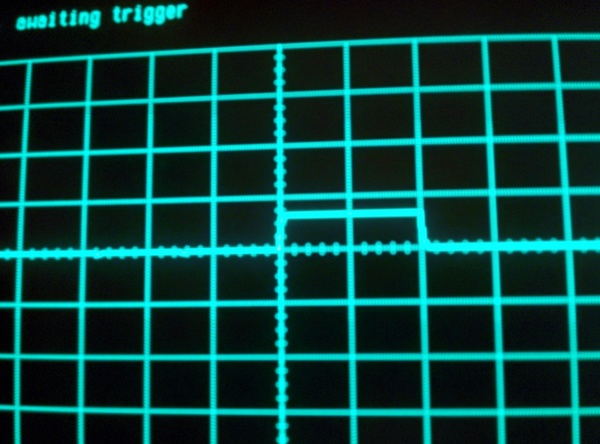
Below is a scope capture of what you should see on the SCR gate. If I recall the vertical scale is 2v/div, time is 50ms/div.
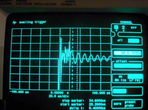
Scope capture of what the trigger pulse going to the bulb should look like. My scope only goes to +/-200v, the pulse should probably peak closer to -250v. Notice the rise time - a couple microseconds at most!
Anyway, I posted this here in hopes it de-mystifies the workings of these things a bit. They were designed some time ago, all the components are through-hole and the board is only 2 layers - both in your favor for reverse engineering and repairing! Obviously not all will fail in the same way but the circuit is not terribly complicated and with a little patience and an old o'scope you can trace out the area of interest. Have fun!
