DIY Current Meter
Current Meter for your Station
Most ham radio transceivers run off 12 VDC, which we provide with various types of power supplies. For quite a few years I used a cheap switching power supply as seen below. You can find them by searching ebay for something like "12v 30a power supply" and while your first thought might be, "crap, I bet that is going to create all kinds of noise on HF!" I did not experience that at all.
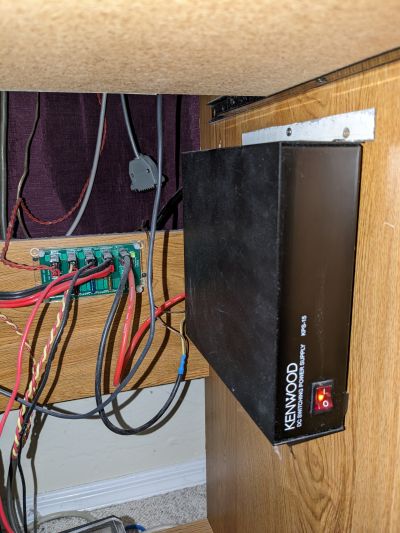
I eventually scored a used Kenwood KPS-15 and switched to using that. It's a very nice power supply, although there was no change in noise floor or spurs that I noticed - further reinforcing the goodness of those cheap switchers! Here it is, installed under my radio table.
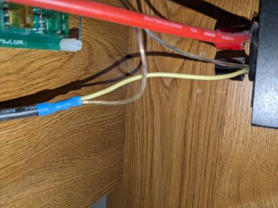
What do both of these supplies have in common? Among other things, they have no current display and while that's not the end of the world, it is useful/fun to see the current draw. Maybe you want to estimate how long you can operate off a battery; maybe you just enjoy seeing meters move! It's easy to add this capability if you have some old analog style meters laying around. These meters, also known as galvanometers, respond to current flow; however, they are typically very sensitive going to full scale deflection with 1 mA or 100 uA! The way to do this is with a shunt, basically a short section of higher resistance conductor across which the meter is placed. I just use a section of smaller gauge wire for the shunt, it's the yellow wire in the picture below.
You can calculate how long this wire should be to give you the correct current through the meter using ohms law and the standard resistance of this wire gauge. I did that and the problem was it was off quite a bit - I think there is quite a bit of error in the standard wire resistance and whatever resistance is in this relatively short length of wire that YOU happen to have. It's also usually unknown how much current it will take to drive your meter to full scale. Eaiser than figuring all that out is just determine it empirically using a bench supply to source a known current through the shunt and slowly trimming it till the meter reading matches reality. I ended up with about 5" of I think it's 14 gauge wire. I put this in series with the negative side of the supply. It would work on the positive side too, but then you have +12v going to your meter and that seems more likely to get shorted out or something.
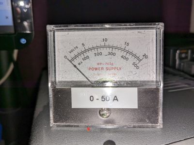
The meter legend doesn't quite match up so I put that sticker on it to remind myself it's 0 to 50 amps not 0 to 500 mA :-)


