Solar tracker
Overview
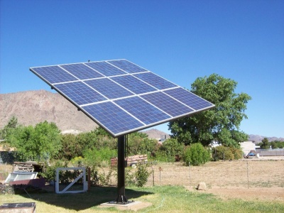
This is the solar array I built for my parents in Kingman, AZ. Perhaps the information here will be useful for anyone else looking to embark on a similar project. There's lots of things I would have done differently and lots of things that could use improvement, but that's how any project goes right?
The goal was to roughly meet our average energy use of 700kWh/month with a grid-tie system. There's no point in generating excess, since our utility only applies it as a credit to future bills (and you pay to maintain connection anyways). I used the data here to predict the ammount of sun we can expect for our area. Since we'd be tracking on one axis with the second manually adjustable, we can figure on average roughly 9 peak hours of sun per day. Sun electronics had some nice 200 watt Suntech panels for about $2.10/watt, and we decided to go with 12 of these for a total of 2.4kW. At 9 peak hours of sun, that gives us around 648kWh per month (not counting line and inverter losses, and heat degradation of the panels). That seemed to be a fair tradeoff, while maintianing a reasonable size. Multiple smaller trackers were also considered, but we have some space limitations as far as unshaded area of the yard goes and 2 separate trackers would have been difficult to fit in.
John Mieding of Mieding & Associates in Bullhead city deserves much of the credit for helping me finalize the CAD drawings into plans and engineering the structure such that it should withstand 90+mph winds that the building codes here require.
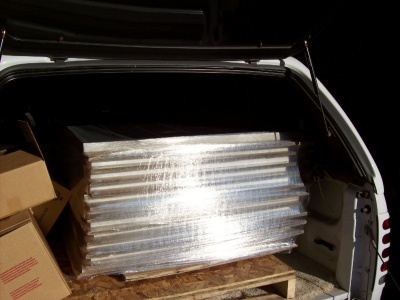
Sun electronics has a warehouse in Phoenix, so we were able to drive down and pick up the panels to save shipping costs. These are pretty good sized panels, weighing about 40lbs each.
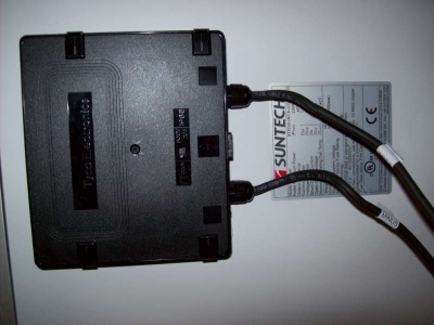
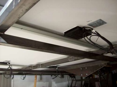
The black box contains three bypass diodes for when the panel is in the nonconducting (in the shade). Each panel has 8 mounting points, which Suntech recommends you use for windy areas. The idea was to put bolts through the frame to hold each panel on. Looking back, I think it would have been better to design around I-beam or U-channel instead of square tubing, but neither were readily available at the time.
Frame & Mast
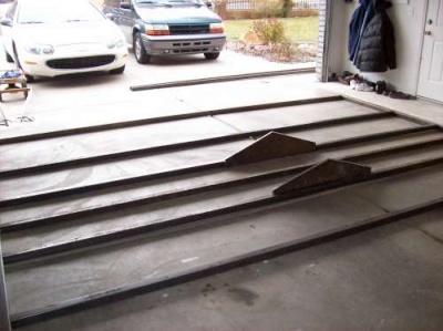
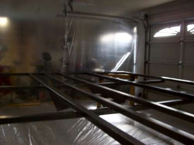
This is the frame to hold all the panels. It's mostly made out of 2" square steel tubing, and a little 115v MIG welder does this stuff very nicely. Above is a picture of it going together, before all the vertical braces were on.
The only shot I have of it completed is during painting. All together, I think it weighed around 500 lbs.
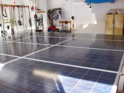
We set all the panels on to see how it would look and to mark where all the mounting holes should go.
And here's one looking from the underneath.
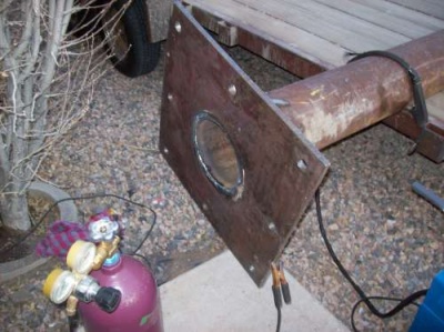
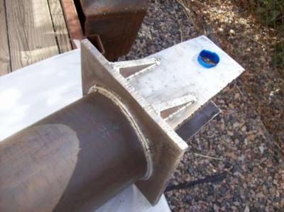
The last main piece was the mast and mounting plate. The same machine shop drilled the 1-1/4" holes that'll mount down to the J-bolts in the foundation. They had a CNC plasma cutter as well, so I had them do the large hole in the center too. It's cool how nice a cut that makes! I beveled the outside of the pipe about 1/4", preheated it all, and welded the heck out of it. There was really only room for the one root weld on the bottom, so I left it at that.
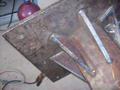
On top, I put 3 welds all around and then all 8 gussets over that. Each gusset was bevelled and preheated to improve weld penetration.
Here's the mount welded to the top. This is mounted in such a way that it'll face exactly true south when everything's bolted to the foundation. On top of the mount in the center, I welded a little 3/4" steel nipple to bring the wires through and screw a junction box onto.
That completes most of the main construction. Everything was sprayed with a black laquer paint to keep things looking nice and prevent rust. Next up is the foundation and inverter installation.
Foundation & Inverter
The hole needed to be about 5' deep by 3' square.
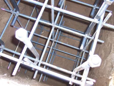
I welded the rebar cage all together since that seemed like the best way to keep everything in alignment. It was very rigid like this which helped keep all the bolts aligned - it was important to match the holes already drilled in the base plate, probably did that in the wrong order :)
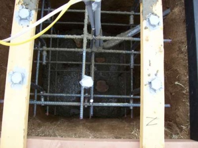
We made the 2x4 jigs to hang the whole thing at the correct height. It was about 1.6 yards of concrete, mixed by hand in a small mixer. Threw a few large stones in there too.
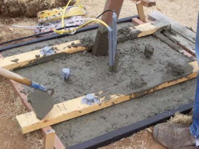
Here's a shot of it almost full. We finished the top and then let it cure for a week before setting the tracker on it.
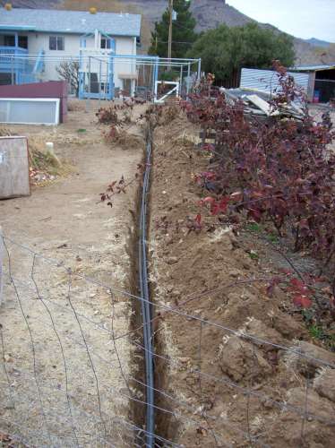
Here is the trench full of conduits. One is bringing DC power from the panels into the inverter, and one is bringing 120 VAC out to run the tracking motors and such. The 3rd one has a piece of coax I thought I might like to use for a camera. It's about a 150ft run, but the PV system runs at around 300 VDC so the resistance losses are pretty insignificant.
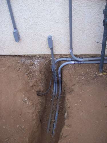
It all terminates at the side of the house. The inverter is mounted in the basement, so we were able to put the conduit straight through the wall into the inverter junction box.
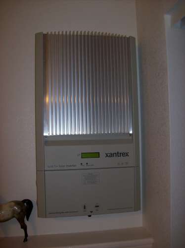
Here's the inverter mounted. This is the Xantrex GT2.8 and so far it's worked very well.
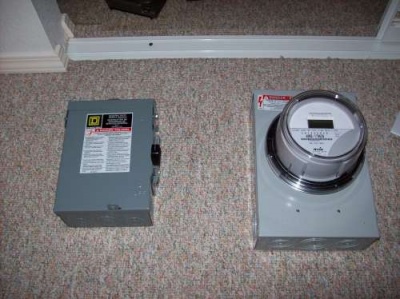
This is the meter and AC disconnect switch. Although our utility allows net metering, they want a second meter to measure just what the PV system is generating. They then replace the main meter with a bi-directional unit that keeps track of how much has been used versus how much has been pushed back into the grid. The inverter outputs 240 VAC and is connected to that square D external disconnect. This is connected to the generation meter which is wired into the breaker panel like any other 240 V circuit. Next is raising the tracker and mounting all the panels.
