Maxon Radio: Difference between revisions
Jump to navigation
Jump to search
(Created page with "==Maxon SD125== These tune from 144 - 178 MHz and work great for APRS stuff. Pinout is as follows: 400px|thumb|right|Pinout") |
No edit summary |
||
| Line 1: | Line 1: | ||
==Maxon SD125== | ==Maxon SD125== | ||
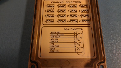
These tune from 144 - 178 MHz and work great for APRS stuff. Pinout | These tune from 144 - 178 MHz and work great for APRS stuff. See image to the right for the pinout. | ||
[[File:MaxonPinout.jpg|400px|thumb|right|Pinout]] | |||
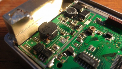
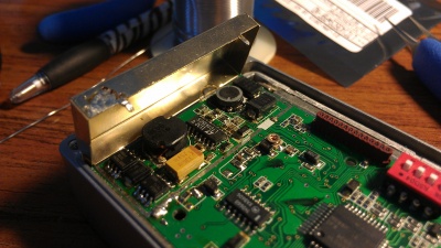
[[File: | I got several of these off ebay used for cheap, but the power supplies were damaged. It appeared like someone had hooked the power up backwards as several of the reverse polarity protection diodes were blown off the board. Several tantalum caps were also damaged. Replacing those fixed one of the radios, but the other one had the switching power supply chip damaged as well as the buck regulator FETs shorted out. That was more work to replace and required removing the shielding can from the logic board - see the pictures. | ||
[[File:MaxonPS1.jpg|400px|thumb|right|Removing the damaged components.]] | |||
[[File:MaxonPS2.jpg|400px|thumb|right|New chips soldered on.]] | |||
Revision as of 19:19, 4 January 2014
Maxon SD125
These tune from 144 - 178 MHz and work great for APRS stuff. See image to the right for the pinout.
I got several of these off ebay used for cheap, but the power supplies were damaged. It appeared like someone had hooked the power up backwards as several of the reverse polarity protection diodes were blown off the board. Several tantalum caps were also damaged. Replacing those fixed one of the radios, but the other one had the switching power supply chip damaged as well as the buck regulator FETs shorted out. That was more work to replace and required removing the shielding can from the logic board - see the pictures.


