Solar tracker: Difference between revisions
No edit summary |
No edit summary |
||
| Line 230: | Line 230: | ||
==Monitoring== | ==Monitoring== | ||
The Xantrex GT-2.8 inverter has an RS-232 port on it that will provide statistics about current system performance. You send it a command, and it responds back with the data. While Xantrex used to provide some 3rd party software to do this, it's no longer supported. Fortunately, I found some very nice documentation describing the available commands and the correct serial port settings. I'll make it available here in case it gets pulled down. The easiest thing then would be to hook a computer directly to it. Since the inverter isn't located anywhere near my server though, I decided to modify a Linksys WRT54GL to connect to it wirelessly instead. | |||
[[File:Linksys_board.jpg|border|400px]] | |||
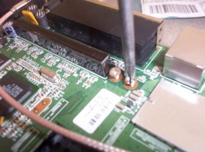
This particular model router has an internal RS-232 port that can be easily accessed if you use the OpenWRT firmware. There's an unpopulated header on the main board, and pinouts are available [http://wiki.openwrt.org/toh/linksys/wrt54g# here]. The blue face of the case just pops forward and then the board will slide out (after unscrewing the antennas). Unscrew the board from the bottom as shown and solder a 2 x 5 header into the board. | |||
[[File:Linksys_levelshifter-500.jpg|border|400px]] | |||
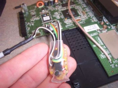
You'll need to build a levelshifter to convert the CMOS 3.3V levels to RS-232 levels (+-12V) using a MAX3232 chip. There's a 3.3V pin brought out on the header, so you'll have something to power it with too. I shrinkwrapped mine to keep it from shorting out anything inside the router since it'll just be flopping around in there. The cable going off to the left of the picture is the serial cable we'll connect to the inverter. Wire a serial connector onto the end. The inverter is expecting a straight-through cable, so don't cross the TX and RX lines :-). Now reflash the router with the OpenWRT firmware and configure it to connect to the wireless network as a client and set it up with a static IP. I run the following cgi script to query the inverter and make the data available as a simple HTTP file. | |||
<nowiki> | |||
#!/bin/ash | |||
echo "Content-Type: Text/plain" | |||
echo "" | |||
# Kill any pre-existing versions of head | |||
pidof head | xargs -r kill -9 | |||
# Call head and send it into the background | |||
head -6 /dev/tts/1 > /www/xantrex/data.txt & | |||
sleep 1 | |||
# Send each query | |||
echo -e "MEASIN?\r" > /dev/tts/1 | |||
echo -e "MEASOUT?\r" > /dev/tts/1 | |||
echo -e "KWHTODAY?\r" > /dev/tts/1 | |||
echo -e "KWHLIFE?\r" > /dev/tts/1 | |||
echo -e "MEASTEMP?\r" > /dev/tts/1 | |||
echo -e "TIME?\r" > /dev/tts/1 | |||
sleep 1 | |||
# Write out the file | |||
cat /www/xantrex/data.txt | |||
# Delete the file, we don't need it | |||
rm /www/xantrex/data.txt | |||
</nowiki> | |||
It's probably not the most elegant solution, but was the quickest way I could come up with to do it, and it's worked fine. Now you can use a php script to grab that file, parse it, and stick it in a database. | |||
The real-time statistics for the system can be found at [http://solar.ad7zj.net solar.ad7zj.net]. The graphs are dynamically generated using PHP, and the little meters are the real-time conditions (they update every 5 minutes). The real-time meters are dependant on our DSL connection being up, so if it doesn't seem to be updating, that's probably why. The power graphs and historical data is cached locally on the linksys router so it will not be lost if the connection is down. I've posted the code here on github: [https://github.com/AD7ZJ/PVMonitor link] | |||
Latest revision as of 05:03, 21 January 2018
Overview
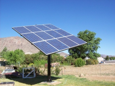
This is the solar array I built for my parents in Kingman, AZ. Perhaps the information here will be useful for anyone else looking to embark on a similar project. There's lots of things I would have done differently and lots of things that could use improvement, but that's how any project goes right?
The goal was to roughly meet our average energy use of 700kWh/month with a grid-tie system. There's no point in generating excess, since our utility only applies it as a credit to future bills (and you pay to maintain connection anyways). I used the data here ![]() to predict the amount of sun we can expect for our area. Since we'd be tracking on one axis with the second manually adjustable, we can figure on average roughly 9 peak hours of sun per day. Sun electronics had some nice 200 watt Suntech panels for about $2.10/watt, and we decided to go with 12 of these for a total of 2.4kW. At 9 peak hours of sun, that gives us around 648kWh per month (not counting line and inverter losses, and heat degradation of the panels). That seemed to be a fair trade off, while maintaining a reasonable size. Multiple smaller trackers were also considered, but we have some space limitations as far as unshaded area of the yard goes and 2 separate trackers would have been difficult to fit in.
to predict the amount of sun we can expect for our area. Since we'd be tracking on one axis with the second manually adjustable, we can figure on average roughly 9 peak hours of sun per day. Sun electronics had some nice 200 watt Suntech panels for about $2.10/watt, and we decided to go with 12 of these for a total of 2.4kW. At 9 peak hours of sun, that gives us around 648kWh per month (not counting line and inverter losses, and heat degradation of the panels). That seemed to be a fair trade off, while maintaining a reasonable size. Multiple smaller trackers were also considered, but we have some space limitations as far as unshaded area of the yard goes and 2 separate trackers would have been difficult to fit in.
John Mieding of Mieding & Associates in Bullhead city deserves much of the credit for helping me finalize the CAD drawings into plans and engineering the structure such that it should withstand 90+mph winds that the building codes here require.
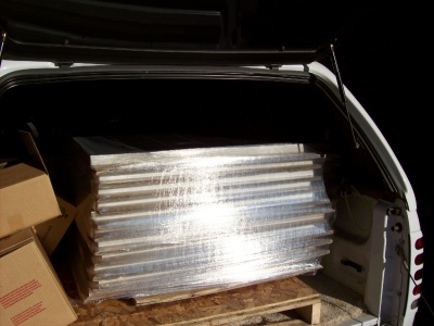
Sun electronics has a warehouse in Phoenix, so we were able to drive down and pick up the panels to save shipping costs. These are pretty good sized panels, weighing about 40lbs each.
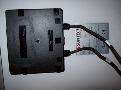
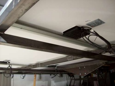
The black box contains three bypass diodes for when the panel is in the nonconducting (in the shade). Each panel has 8 mounting points, which Suntech recommends you use for windy areas. The idea was to put bolts through the frame to hold each panel on. Looking back, I think it would have been better to design around I-beam or U-channel instead of square tubing, but neither were readily available at the time.
Hinge Construction
A solar tracker needs to pivot in two dimensions - one to account for the change in the sun's elevation and one for the daily movement. A "Polar mount" allows tracking of the daily movement with a single actuator, and as such is the method of choice for solar trackers. I originally was hoping to use a mount from an old C band satellite dish, but it quickly became apparent that wouldn't be strong enough for an array of this size. In the end I decided to fabricate one from scrap metal.
In fact almost all the material for this project was sourced from the local scrapyard. At the time, they were selling steel for 40c/lb which was a lot cheaper than buying it new (and some of what they had was in like-new condition anyways). Going through the scrap yard and looking for stuff was also great fun, and the design was constantly being tweaked to make use of the cheapest available materials. The main items were the 8" schedule 80 pipe that makes up the mast and the 5/8" steel plate that makes up the base and parts of the polar mount. That steel plate was very heavy and we had no way to move it around once it was loaded on the trailer. I used a torch to cut it into the necessary pieces without ever moving it off the trailer (thanks to Don Kay for letting us borrow that).
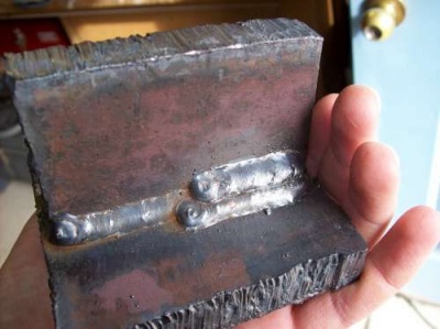
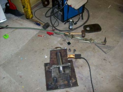
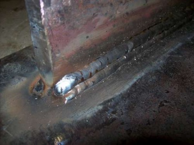
I was a little concerned about how well my little 220v MIG welder would penetrate this heavy steel, so I did some practice runs. I beveled about 1/4" off each edge and preheated the metal with a torch to around 400F.
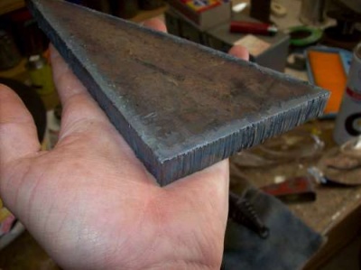
It seems to penetrate pretty well though and after a few opinions from other welders, I decided it's probably good enough :-). I started by cutting out all the pieces from the 5/8" steel plate. You have to be pretty steady with the torch to get a decent cut. I used a piece of angle iron as a guide to keep a nice straight cut. It takes a long time to grind something this thick, so I had a lot of motivation to make clean cuts with the torch!
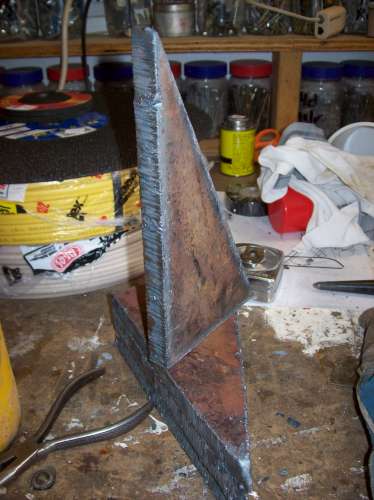
These guys will go between the base plate and the mast for additional support.
One more for a bit of a size reference...
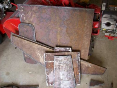
One more of all the pieces together. The large square piece in the back will be the base, the long piece with rounded corners will be one of the endcaps, the two long, triangular pieces will be the frame mounts, and the 3 pieces in the front make up the base and sides of the polar mount.
Here you can see the polar mount coming together. That's a 2" hardened steel pin going in between - it took about 20 minutes to cut through it with a chopsaw. We had a local machine shop bore out the holes in each plate and cut a grease groove in the bearing surface. Although it really won't move much (this will be the hinge too allow for manual elevation adjustment), it's probably still a good idea to keep everything in good shape. There will be zerk fittings on top of each plate. The real trick here was trying to keep those plates perfectly perpendicular to the base (and parallel to each other) while welding them on. There's only a few thousands clearance between the bearing surfaces and that pin, so it's got to be pretty close. Actually it was kind of a big headache, and next time I'm sure it'd be better done with flange bearings bolted to the plates since they allow quite a bit of freedom in alignment.
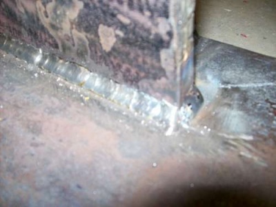
Here's a few pictures of the welds going down on the polar mount assembly. Again, I beveled about 1/4" off each side of everything and preheated to around 400F with the torch to maximize penetration. In the end, there was lots of discoloration on the opposite side of the weld (which usually indicates decent penetration) so it was worth it.
And then 2 more welds on top of the root weld...
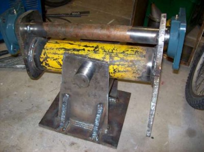
Now here's the hinge tube in between the plates. This will be on the north-south axis, and the array will track into and out of the picture. It's at about 40 degrees of elevation in the picture, so that's where it would be sometime in the spring or fall.
And now, these pieces get added to the hinge tube. That rod on the left is the other piece of that 2" steel pin I mentioned earlier. We had 2" holes bored through each of those endcaps, and the pin slides through and is welded in place. The whole array will then pivot on that pin.
Here's the endcap welded on. You can see the steel pin "tacked" in the far right.
And here it is all finished! You can see how the far right endcap is pulled in from the weld shrinkage is. The array frame will bolt to each of those flange bearings in the center. The flanges are built such that the bearing can pivot about 15 degrees each way, so they don't have to be aligned perfectly.
Frame & Mast
This is the frame to hold all the panels. It's mostly made out of 2" square steel tubing, and a little 115v MIG welder does this stuff very nicely. Above is a picture of it going together, before all the vertical braces were on.
The only shot I have of it completed is during painting. All together, I think it weighed around 500 lbs.
We set all the panels on to see how it would look and to mark where all the mounting holes should go.
And here's one looking from the underneath.
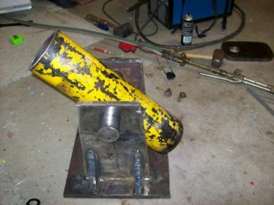
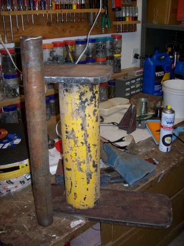
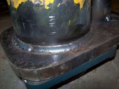
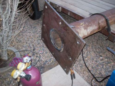
The last main piece was the mast and mounting plate. The same machine shop drilled the 1-1/4" holes that'll mount down to the J-bolts in the foundation. They had a CNC plasma cutter as well, so I had them do the large hole in the center too. It's cool how nice a cut that makes! I beveled the outside of the pipe about 1/4", preheated it all, and welded the heck out of it. There was really only room for the one root weld on the bottom, so I left it at that.
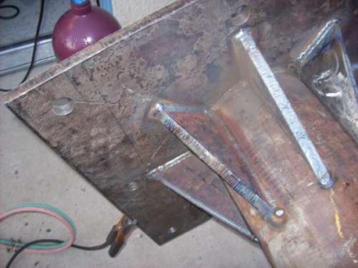
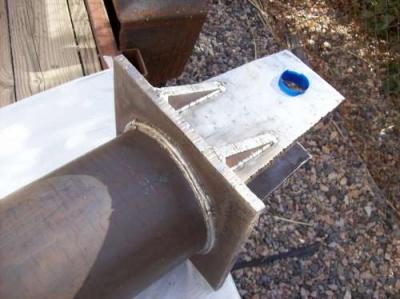
On top, I put 3 welds all around and then all 8 gussets over that. Each gusset was bevelled and preheated to improve weld penetration.
Here's the mount welded to the top. This is mounted in such a way that it'll face exactly true south when everything's bolted to the foundation. On top of the mount in the center, I welded a little 3/4" steel nipple to bring the wires through and screw a junction box onto.
That completes most of the main construction. Everything was sprayed with a black laquer paint to keep things looking nice and prevent rust. Next up is the foundation and inverter installation.
Foundation & Inverter
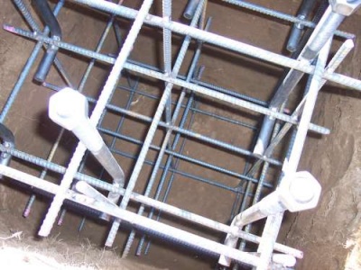
The hole needed to be about 5' deep by 3' square.
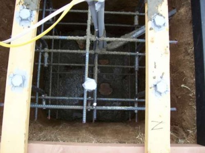
I welded the rebar cage all together since that seemed like the best way to keep everything in alignment. It was very rigid like this which helped keep all the bolts aligned - it was important to match the holes already drilled in the base plate, probably did that in the wrong order :)
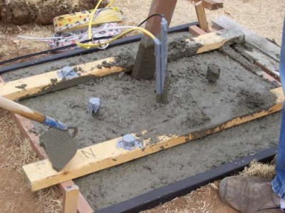
We made the 2x4 jigs to hang the whole thing at the correct height. It was about 1.6 yards of concrete, mixed by hand in a small mixer. Threw a few large stones in there too.
Here's a shot of it almost full. We finished the top and then let it cure for a week before setting the tracker on it.
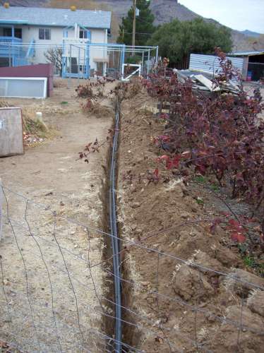
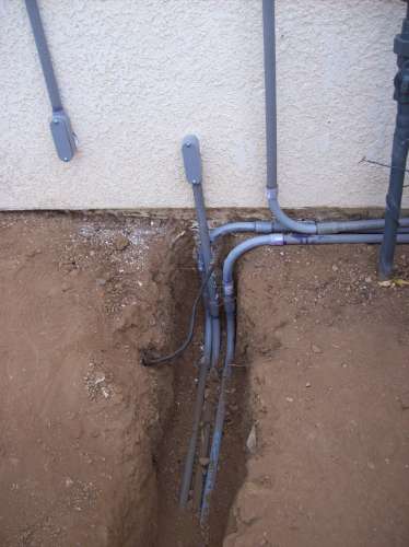
Here is the trench full of conduits. One is bringing DC power from the panels into the inverter, and one is bringing 120 VAC out to run the tracking motors and such. The 3rd one has a piece of coax I thought I might like to use for a camera. It's about a 150ft run, but the PV system runs at around 300 VDC so the resistance losses are pretty insignificant.
It all terminates at the side of the house. The inverter is mounted in the basement, so we were able to put the conduit straight through the wall into the inverter junction box.
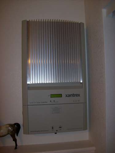
Here's the inverter mounted. This is the Xantrex GT2.8 and so far it's worked very well.
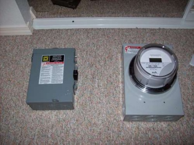
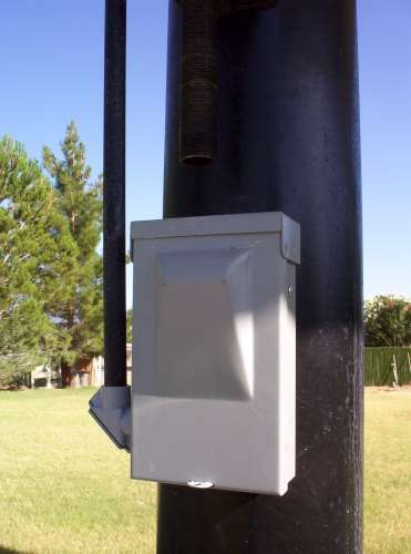
This is the meter and AC disconnect switch. Although our utility allows net metering, they want a second meter to measure just what the PV system is generating. They then replace the main meter with a bi-directional unit that keeps track of how much has been used versus how much has been pushed back into the grid. The inverter outputs 240 VAC and is connected to that square D external disconnect. This is connected to the generation meter which is wired into the breaker panel like any other 240 V circuit. Next is raising the tracker and mounting all the panels.
Final Assembly & Raising
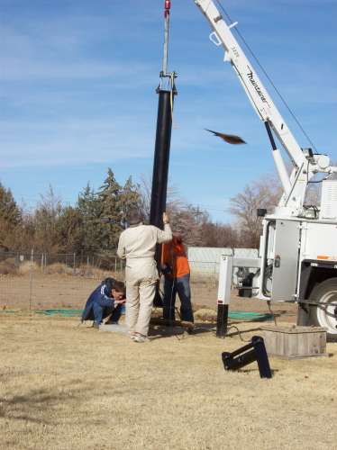
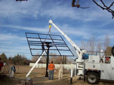
Our neighbor was kind enough to bring over his work truck on the weekend to assist in setting everything up on the foundation. The mast had to be lifted into place and bolted down, and then the frame mounted on top. We put tar on the bottom of the base to help protect it from the water. Not that 5/8" of steel is going to rust through anytime soon, but it's probably a good idea. :) One of the holes didn't quite fit over the bolt and had to be elongated by about 1/16" but other than that, everything went pretty smoothly.
The hinge tube and bearings were all mounted, so once the frame and everything was lifted into position, that 2" steel pin was slid in and held everything in place.
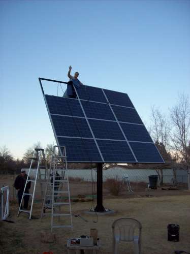
Next up was installing the panels. They don't weigh that much but they're bulky and not that easy to carry up a ladder. We used moving blankets as padding, and then slid them up the ladder and into place using ropes. There are 8 bolts that hold each panel in place. The holes in the panels are elliptical so you have a little room to move things around and get them all even.
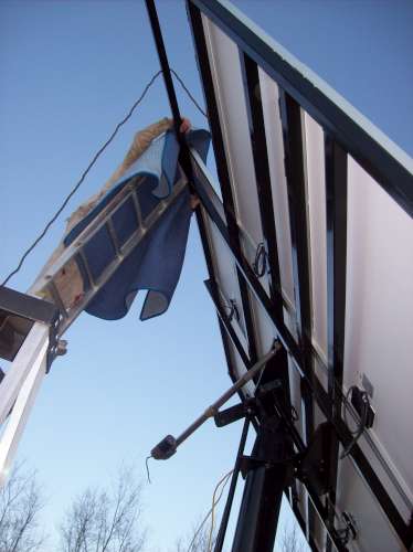
Here's a view from the back. Notice the electric linear actuator; the original intention was to use that to drive the array. As it turned out, it wasn't really up to the job as this whole thing is pretty heavy. I think the biggest problem was the slop introduced by it. In windstorms, the array would wobble an uncomfortable amount because of the slop in the gears :-). The temporary solution was to replace it with a 2" steel pipe to lock the array in place in the noon-day position until I could come up with something more stout.
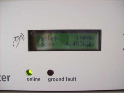
I had to take a picture of the inverter when it first powered up and came online. That actually ended up being the day before I had to go back to school, so the project halted here for a few months. The tracking controller and hydraulic actuator was added later.
Hydraulics
As mentioned previously, the electric actuator wasn't up to the task of moving the array. The necessary parts for a small hydraulic system can be had from surpluscenter.com for not much more than a larger electric actuator would have cost. Since there's very little slop in a hydraulic system and it's certainly plenty strong, we decided to go that route. The original intention was to use that big oil filter as a tank as recommended by a local hydraulic guy, however that didn't end up working...
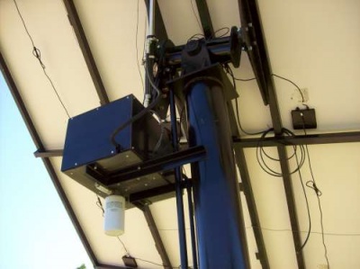
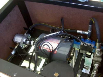
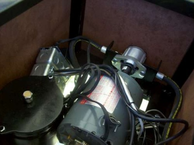
Here is the whole setup. Using the filter as a tank didn't seem to work out very well... I could never get all the air out of it. When used as a tank, the oil level needs to rise up and down as the cylinder expands and contracts. It turns out need a bit of pressure to pull the oil through the filter element - gravity just won't do the trick, so the center of the filter was constantly being sucked too low and the outside overflowing. I ended up welding a small tank and screwing it to the top of the filter to keep it always full of oil. The pump is a small volume gear pump, and the pressure regulator is set to around 1000 psi. The blue rectangle on the right side is a double-acting solenoid. It's driven by two 115 VAC solenoids. Powering one drives the ram in while powering the other drives it out. On the outlet of the solenoid is a needle valve to adjust the speed of the ram. The goal here is a smooth, slow movement so it's tightened down a lot. This particular valve allows free flow in one direction, which caused a little bit of confusion initially :-)
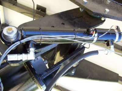
This is the ram installed. It's a 20" stroke x 2" bore. The wires tied to it are connected to the limit switches. This allows the controller to determine when the array has reached the extent of it's travel.
Another shot of the hydraulic system. The two junction boxes house relays to control the motor and solenoids. The white wire runs down to the controller, which drives these relays with 12v.
Here's the controller mounted at the base of the mast, it's a modified Square-D disconnect box.
Controller
To make the array track the sun and sequence the hydraulics, I designed a custom PIC-based controller. The switches on top allow manual control of the array.
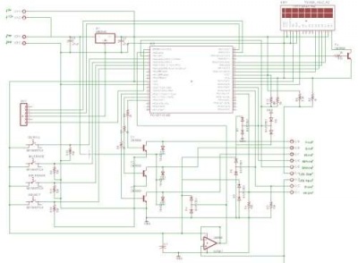
It's powered by a 12 VDC wallwart which is located up in the hydraulics box. The large white wire is connected to the relays and the large gray wire is connected to the LED sensors. The design is based on a schematic by Ross Wheeler and modified a bit to work with the hydraulics. The schematic is shown below (see sources for the actual design).
The sensor consists of two large green LEDs wired back to back and mounted facing the sun at an angle. Any LED will produce a tiny bit of power when exposed to light, but green ones seem to produce the most. In full sun they produce a little over 1 volt but a very small current. The idea is that when they are both seeing an equal amount of sun, the voltage across will be zero.
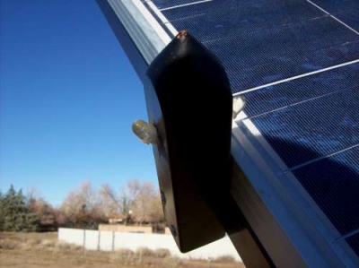
Here's how the LEDs are mounted. The specific location isn't really important, but we figured the side was the least likely place for birds to sit on it. If the sun is behind the array, the voltage will be negative. Conversely if the sun is ahead of the array, the voltage will be positive. To allow detection of this negative voltage, the LEDs are biased up slightly. The LED output is buffered through an LM358 op-amp and then sampled directly by the PIC's onboard ADC. One problem I had was that in the mornings when the sun is significantly behind the tracker, the LEDs can pull the opamp's input below the negative rail. This results in weird behavior (like the output going high) so a diode should be put between the LED bias and the LED input. The voltage drop across the diode still allows some swing below the bias, but keeps the input from going negative. The dual diode packages (D4 - D8) provide ESD protection for any external inputs.
There are 4 pushbutton switches and a 16 x 2 LCD for a basic user interface with the controller. The 6-pin header fits into the PICkit 2 ICSP for easy reprogramming.
To actually move the array, the controller has to sequence the hydraulics. There are 3 relays up in the hydraulics box; two control the solenoids, and one controls the pump motor. 12 VDC is supplied to the relay coils at all times and transistors T1 - T3 sink the current to ground to turn on the relay. Diodes D1 - D3 protect the transistors from the inductive voltage spike seen after shutoff.
Another problem I ran into was that the motor I chose didn't have quite enough starting torque to overcome the hydraulic pressure. To avoid having to come up with another motor, I had the controller open the desired solenoid a few hundred ms before switching on the motor. This allows the pressure to bleed off enough that the motor can start up without any issue. It sounds like a hack, and it kind of is, but the system is going on ten years of trouble free operation so you can't laugh at it too much!
Another "gotcha" was the extreme sensitivity to noise. There's probably 15ft of wire between the sensors and the controller, and that was picking up the ambient 60 Hz hum. This really screwed up the accuracy and rendered it almost useless. I ended up solving this problem by using shielded wire and tying the shield (at one end) to the circuit board ground plane.
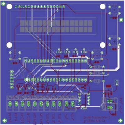
Here's the board layout I came up with (again see sources for the real design). I used some surface mount parts since they're cheaper and keep things a lot smaller. The size could be reduced significantly more by using a surface mount PIC, but I thought it might be nice to be able to easily replace it should the need arise.
Software
The software is written in BASIC for the PICBasic Pro compiler. It has a very simple user interface to allow changing delays, changing the neutral point, forcing an immediate track, and just generally see what's going on. At the time I was just starting out with PICs and used PICbasic Pro as a compiler. The software outputs signals to control the LCD display and hydraulics, and monitors the LED sensor input and four buttons that control the user interface:
- Menu
- Sequences through the menus
- Track
- Forces the software to re-center the array
- Increase
- Increases whatever value is currently on the menu
- Decrease
- Decreases whatever value is currently on the menu
It has the following menus:
- Home page
- Shows the current mode (auto or manual) and counts down to the next track operation.
- Sensor Value
- Displays the raw ADC value (useful for testing the sensor and buffer circuitry)
- Center position
- Displays the ADC value that will be interpreted as facing directly into the sun.
- Center time (s)
- Displays the time in seconds for the array to move back to the center from the full west position. This allows the array to be flat (or nearly so) to avoid being hit by the sprinkler.
- Night Dly(h:m)
- Displays how much time the array will spend in the flat position before moving back to the full east position.
- Update Rt (m:s)
- Displays how often the software will re-center the array to face the sun.
- Press track to move safe
- When the "Track" button is pressed, the array will move all the way over to the west position. This is the position giving the hydraulic ram the most mechanical advantage, and is used if very strong winds are expected.
Monitoring
The Xantrex GT-2.8 inverter has an RS-232 port on it that will provide statistics about current system performance. You send it a command, and it responds back with the data. While Xantrex used to provide some 3rd party software to do this, it's no longer supported. Fortunately, I found some very nice documentation describing the available commands and the correct serial port settings. I'll make it available here in case it gets pulled down. The easiest thing then would be to hook a computer directly to it. Since the inverter isn't located anywhere near my server though, I decided to modify a Linksys WRT54GL to connect to it wirelessly instead.
This particular model router has an internal RS-232 port that can be easily accessed if you use the OpenWRT firmware. There's an unpopulated header on the main board, and pinouts are available here. The blue face of the case just pops forward and then the board will slide out (after unscrewing the antennas). Unscrew the board from the bottom as shown and solder a 2 x 5 header into the board.
You'll need to build a levelshifter to convert the CMOS 3.3V levels to RS-232 levels (+-12V) using a MAX3232 chip. There's a 3.3V pin brought out on the header, so you'll have something to power it with too. I shrinkwrapped mine to keep it from shorting out anything inside the router since it'll just be flopping around in there. The cable going off to the left of the picture is the serial cable we'll connect to the inverter. Wire a serial connector onto the end. The inverter is expecting a straight-through cable, so don't cross the TX and RX lines :-). Now reflash the router with the OpenWRT firmware and configure it to connect to the wireless network as a client and set it up with a static IP. I run the following cgi script to query the inverter and make the data available as a simple HTTP file.
#!/bin/ash

echo "Content-Type: Text/plain"
echo ""

# Kill any pre-existing versions of head
pidof head | xargs -r kill -9

# Call head and send it into the background
head -6 /dev/tts/1 > /www/xantrex/data.txt &
sleep 1

# Send each query
echo -e "MEASIN?\r" > /dev/tts/1
echo -e "MEASOUT?\r" > /dev/tts/1
echo -e "KWHTODAY?\r" > /dev/tts/1
echo -e "KWHLIFE?\r" > /dev/tts/1
echo -e "MEASTEMP?\r" > /dev/tts/1
echo -e "TIME?\r" > /dev/tts/1

sleep 1

# Write out the file
cat /www/xantrex/data.txt

# Delete the file, we don't need it
rm /www/xantrex/data.txt
It's probably not the most elegant solution, but was the quickest way I could come up with to do it, and it's worked fine. Now you can use a php script to grab that file, parse it, and stick it in a database.
The real-time statistics for the system can be found at solar.ad7zj.net. The graphs are dynamically generated using PHP, and the little meters are the real-time conditions (they update every 5 minutes). The real-time meters are dependant on our DSL connection being up, so if it doesn't seem to be updating, that's probably why. The power graphs and historical data is cached locally on the linksys router so it will not be lost if the connection is down. I've posted the code here on github: link
