Difference between revisions of "New Flight Computer"
| (4 intermediate revisions by the same user not shown) | |||
| Line 1: | Line 1: | ||
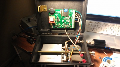
| − | This is the new flight computer we are in the process of developing. This page serves to document the current progress. | + | [[File:IMAG0602.jpg|400px|thumb|right|Assembled Package]] This is the new flight computer we are in the process of developing. This page serves to document the current progress. |
| + | |||
== Progress == | == Progress == | ||
A high level view of remaining features to be implemented | A high level view of remaining features to be implemented | ||
| − | * | + | * Configuration Storage |
| − | ** | + | ** currently callsigns and other settings are embedded in the code. Eventually we want to have these pulled from a file on the SD card so a code rebuild is not necessary to change them. |
| − | * | + | * DTMF decoding |
| − | ** | + | ** currently the CML modem chip is only being used to generate packets but is actually capable of decoding DTMF as well. |
| − | |||
| − | + | == Features == | |
| − | |||
| − | |||
* Single board for flight computer and beacon use | * Single board for flight computer and beacon use | ||
| Line 23: | Line 21: | ||
** Ability to add additional sensors externally would be nice | ** Ability to add additional sensors externally would be nice | ||
** Log battery voltage | ** Log battery voltage | ||
| − | |||
* Ability to receive DTMF/packet commands in flight | * Ability to receive DTMF/packet commands in flight | ||
| − | ** (clear logging, begin logging, beacon reset, GPS reset, | + | ** (clear logging, begin logging, beacon reset, GPS reset, etc) |
* Ability to configure volatile parameters via menu or file | * Ability to configure volatile parameters via menu or file | ||
** Call Sign | ** Call Sign | ||
| Line 40: | Line 37: | ||
An SD card is hooked up to the second built-in SPI port. The SD standard allows for a slower (but simpler) SPI interface to the cards. The trick to this is implementing the FAT filesystem in software, but thanks to the ChanFS FAT library this has been made pretty easy. | An SD card is hooked up to the second built-in SPI port. The SD standard allows for a slower (but simpler) SPI interface to the cards. The trick to this is implementing the FAT filesystem in software, but thanks to the ChanFS FAT library this has been made pretty easy. | ||
| − | A Trimble Copernicus GPS engine is connected to one of the built-in UARTs. This outputs standard NMEA strings and is itself configured over the same serial port. | + | A Trimble Copernicus GPS engine is connected to one of the built-in UARTs. This outputs standard NMEA strings and is itself configured over the same serial port by using the 'loopback' mode to connect the GPS UART to the external UART. |
=== Schematics === | === Schematics === | ||
| Line 49: | Line 46: | ||
The VHF module has a carrier detect output, used to indicate the radio is unsquelched. This is an open collector output, pulled up to 5v internally. This is connected to P0.16 on the LPC2148, which is a 5v tolerant pin so we should be OK with this. | The VHF module has a carrier detect output, used to indicate the radio is unsquelched. This is an open collector output, pulled up to 5v internally. This is connected to P0.16 on the LPC2148, which is a 5v tolerant pin so we should be OK with this. | ||
| + | |||
| + | === Diplexer === | ||
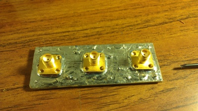
| + | [[File:IMAG0585.jpg|400px|thumb|right|Top of diplexer]] | ||
| + | The diplexer allows the two radios to share a single antenna. It's just a low pass filter filter and high-pass filter to keep the transmitter from desensing the receiver. | ||
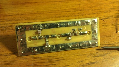
| + | [[File:IMAG0586.jpg|400px|thumb|right|Bottom of diplexer]] | ||
| + | This is the same design ANSR has been flying for a number of years on our old flight computer. I swept it with a network analyzer to get the following plots. | ||
| + | [[File:LowpassResp.png|400px|thumb|none|VHF port magnitude response]] | ||
| + | [[File:HighpassResp.png|400px|thumb|none|UHF port magnitude response]] | ||
== Software == | == Software == | ||
Latest revision as of 22:42, 31 December 2014
This is the new flight computer we are in the process of developing. This page serves to document the current progress.
Progress
A high level view of remaining features to be implemented
- Configuration Storage
- currently callsigns and other settings are embedded in the code. Eventually we want to have these pulled from a file on the SD card so a code rebuild is not necessary to change them.
- DTMF decoding
- currently the CML modem chip is only being used to generate packets but is actually capable of decoding DTMF as well.
Features
- Single board for flight computer and beacon use
- AX.25 packet capability for data transmission
- On-board landing prediction based on wind data gathered during ascent
- Auto flight start detection to begin logging for prediction
- Logging
- Mass storage support for easy access to flight data
- Internal and external temp sensors
- Ability to add additional sensors externally would be nice
- Log battery voltage
- Ability to receive DTMF/packet commands in flight
- (clear logging, begin logging, beacon reset, GPS reset, etc)
- Ability to configure volatile parameters via menu or file
- Call Sign
- Beacon time slotting
- Customization of the status string
Hardware
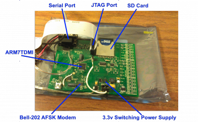
The hardware is based around the NXP (formerly Phillips) LPC2148 - a microcontroller built on the ARMv7 architecture. Benefits are low cost, generous amounts of flash memory and RAM, and plenty of I/O. The chip is driven off a 12 MHz crystal which is multiplied up to 24 MHz by the onboard PLL. This particular processor can run at up to 60 MHz.
Peripherals
A CML Micro CMX678 bell 202 modem IC is used to generate the AFSK AX.25 packet that modulates the radio. This talks to the uC using one of the built-in SPI ports (SPI0). Setup of this IC is pretty simple, and the bitstream is simply shifted out to it via SPI commands.
An SD card is hooked up to the second built-in SPI port. The SD standard allows for a slower (but simpler) SPI interface to the cards. The trick to this is implementing the FAT filesystem in software, but thanks to the ChanFS FAT library this has been made pretty easy.
A Trimble Copernicus GPS engine is connected to one of the built-in UARTs. This outputs standard NMEA strings and is itself configured over the same serial port by using the 'loopback' mode to connect the GPS UART to the external UART.
Schematics
The schematics and board layout is done in Eagle, which can be found under the 'Hardware' folder in the Git repository (need to add link)
Radios
2 Maxon data radios are used to provide APRS downlink as well as the crossband repeater capability. An SD125U2 (UHF) serves as the data and void downlink and and SD125V2 (VHF) serves as the voice uplink. The UHF module needs to switch between two frequencies to avoid having the data packets transmit on the voice frequency. This will be accomplished using an open drain output on the flight computer board wired to the #1 DIP switch. When the output is 'closed' channel 2 is selected - when open, channel 1 is selected.
The VHF module has a carrier detect output, used to indicate the radio is unsquelched. This is an open collector output, pulled up to 5v internally. This is connected to P0.16 on the LPC2148, which is a 5v tolerant pin so we should be OK with this.
Diplexer
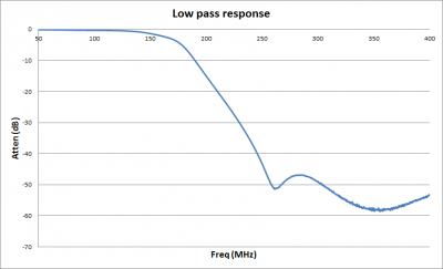
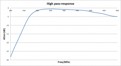
The diplexer allows the two radios to share a single antenna. It's just a low pass filter filter and high-pass filter to keep the transmitter from desensing the receiver.
This is the same design ANSR has been flying for a number of years on our old flight computer. I swept it with a network analyzer to get the following plots.
Software
The software is written primarily in C++, with the exception of the basic startup routines to initialize the hardware and setup the C++ runtime. I use a port of GCC for arm, put together by CodeSourcery (now MentorGraphics). The 'lite' version is fine, all you get by paying for the other versions is an IDE and the startup routines - we're going to do everything with a makefile, which is really superior to a project file for an IDE anyways (at least in my opinion :). Eclipse can easily run make to begin the build process or you can run it from the command line if you prefer.
Build Environment & Procedures
Since the software is built using a makefile, the build environment setup is very simple. I use Ubuntu Desktop as the host platform. The CodeSourcery compiler is available for windows as well however, so with a few tweaks to the makefile it should also build under Cygwin. I like to use the Eclipse editor since it has integrated in-circuit debugging capability with GDB and OpenOCD. Install the codesourcery version 4.5.2 lite package and ensure it gets added to your $PATH environment variable. Run 'make' in the directory to start the build.
The code can be cloned from github:
- Arm7 Library: https://github.com/AD7ZJ/arm7lib
- Application Software: https://github.com/AD7ZJ/ANSR-Flight-Computer
You'll want to build the library first as the application needs it as a dependency. Run 'make' in the directory to start the build. Assuming it builds successfully, you should have a file called libarm7lib.a in the project directory.
Now the application software can be built. The makefile currently expects the libary in the relative directory ../arm/arm7lib however that is easy to change if necessary.
Debugging
The application is setup for debugging using the Eclipse IDE which natively works with GDB, and the Zylin plugin to interface with OpenOCD. First thing is to make sure you have OpenOCD installed. Then install the Zylin Eclipse plugin from within Eclipse by going to Help->Install New Software... and click Add. Enter something like "Zylin" for the name, and then for the location put http://opensource.zylin.com/zylincdt Click OK and it should then find the Zylin Embedded CDT - proceed with the install of this. Eclipse will need to restart after this.
It is easiest to setup OpenOCD as an external tool to run from within Eclipse - this saves you from typing in the command line arguments each time you want to run it. To do this, from the C++ perspective click Run->External Tools->External Tool Configurations... Create a new configuration and put in the full path to the OpenOCD bin's location as well as for the working directory. In my case, the location is /usr/bin/arm-toolchain/bin/openocd and the working dir is /usr/bin/arm-toolchain/bin. For arguments, put in -f /home/elijah/projects/arm7_app/openocd.cfg Obviously this has to be adjusted to suit your system, but the important thing is to get it pointed at the openocd.cfg file. This can be a path relative to your workspace dir.
Next thing to do is setup the debug configuration. This should be already setup in the project's config file, but for future reference here is how to do it. Switch to the debug perspective to do this, click on the arrow next to the bug, and select Debug Configurations... There should be an option in the menu on the left for Zylin Embedded (Native). Create a new configuration under this, and start filling out the boxes as follows:
- C++ Application: FlightComputer.elf This is the file that will be loaded into GDB for symbol info.
Under the debugger tab:
- Set the debugger dropdown to 'Embedded GDB'
- Set GDB Debugger: /home/elijah/CodeSourcery/Sourcery_G++_Lite/bin/arm-none-eabi-gdb Obviously adjust this to the full path of wherever you installed the CodeSourcery toolchain.
Under the Commands tab:
- In the initialization commands put 'target remote localhost:3333' without the quotes
- In the run commands box, put the following:
monitor reset halt

monitor wait_halt

monitor gdb_breakpoint_override hard

monitor poll

monitor arm7_9 fast_memory_access enable

monitor arm7_9 dcc_downloads enable

monitor flash probe 0

monitor flash write_image erase /home/elijah/projects/arm7_app/FlightComputer.bin

monitor reset halt
Useful References
http://www.gnu.org/software/libc/manual/html_node/Rounding-Functions.html#Rounding-Functions
http://openocd.sourceforge.net/doc/html/General-Commands.html
http://openocd.sourceforge.net/doc/html/CPU-Configuration.html
